Getting my 1994 W124 E200 to run again

From other posts like this one, I seem to always be complaining about the 209 E200 W211, The thing i never mentioned is that I have an even older Mercedes E200, A W124 that has been parked for 8 years and decided just now to revive it.

for one, there is a water leak in the cooling system, for another, it has no gas in it, and the fuel pump is not working !

I recall from 8 years ago someone telling me “I can smell gas” While the car was parked near us ! So i am guessing, there is a small leak that is leaking out the gas

Not long before it got parked (8 years ago), the car had a serious leak (Leaked a full tank in a day) and I had to change the hose that connected the fuel tank to the fuel pump that is under the car !

Here are the specs, and this is post is all about how I plan to bring this car to life in a few days !

My Mercedes 200 E (W124 – E200)

  • Transmission: 5 Speed manual transmission
  • Engine: 111.940 (Wikipedia) (Check if part is 111 010 8700 on xentry/das)
  • It has that different looking steering wheel and shifter, If i recall right, this variant’s name has the word sport in it (probably sports line), but I am not sure what it was called exactly, I recall this info because I had to get the steering wheel shipped from Poland as no used or new parts dealer has ever seen it before

Diagnostics/OBD2

Well, this 1994 E does have a diagnostics port, but it is nothing like OBD2 (It is OBD1 not 2), it is very easy to read, just connect any LED (use a 12V LED, or adapt an LED for 12V with resistors obviously).

The 16 pin connector can be accessed with banana plugs connecting the LED to the flowing

Pin-3 = ECU (BLINK… LED+Button)
Pin-6 = K-line (BLINK… LED+Button) (Ex: VAG-COM USB reader)
Pin-1 = GND
pin-16 = 12V

The users manual does not go into sufficient detail concerning the (HFM Sequential Multiport Fuel Injection/Ignition System (HFM-SFI))

The OBD plug can be accessed with a scan tool (Ex: HfmScan) using the diagram below, if you insist on going into that rabbit hole, there are adapters (OBD2 to banana) like the one you see here, which connects the OBD connector to the following pins (OBD breakout cable 4 colours)
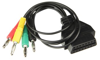
Now, I prefer using the LED method

Degrading wires (Mercedes and Porsche !)

Why I think claiming that the degrading wires were “intentionally installed for easier recycling” is a bullshit attempt to cover Mercedes benz’s unforgivable failure on those models

  • Having an arcing wire right next to the fuel pump is an even worse failure than the failing to predict that the wires will bio degrade
  • Giving a rust insurance of 30 years, and having the wires degrade after 10 ? doesn’t make any sense, You are implicitly telling the consumer you are expecting the car to live for 30 years, having its cables degrade starting after 10 years with the most dangerous ones, and eventually degrading to the extent that fixing it is not feasible contradicts the assumption of expected longevity !
  • Assuming the above is not correct in the sense that not all wires degrade, only those exposed to heat etc… defeats the purpose they claim the wires were scheduled to degrade for

To revisit

When your primary concern is getting it to run, you will come across stuff that needs attention after, here is a small list

  • The wires to the fuel pump need shrink wraps
  • Distilled water to be swapped with antifreeze

Shopping list

I don’t think this will be a long list, but I am mentioning what I needed here so that if you are in a similar situation, this might remind you of what you might need

  • Electrician’s tape
  • Gasoline ! since it probably evaporated
  • A 12V tester (Usually in the form of a screw driver with a wire hanging out from the back to go to ground/Negative)
  • A 12V car battery (The one in the car is 100% toast)
  • Distilled watter for the radiator (Add antifreeze later)
TOYOTA BZ4X

The list of questions and information will probably continue to grow until i end up buying a new electric car, so i will keep updating this list as i find out more about this car.

I am thinking of getting the Toyota BZ4X, So I will be posting my findings here, the order of the questions is counter intuitive, because I always prefer to start at the place that branches most

– Is the Toyota BZ4x exactly the same as the Subaru Solterra ?

  • All the research up to now says they are identical, but i have not been able to validate this conclusion yet

– Which diagnostics software does the car use ?

Why so early with this question ? because the upcoming questions need to adapt to answer this one which provides better questions down the line !

On the Toyota Techstream website, there is a claim that Version 18 works with the BZ4X, I will test this in person hopefully today.

– The BZ4X sold in china is made by GAC MOTOR (FAW no longer makes them), while the one sold in north america is made in Japan, are those cars exactly the same ?

My research up to this point says they should be, but I can’t seem to find any differences besides the battery size

– Cars sharing the e-TNGA platform share what exactly ?

Electric motor location, driver positioning, and battery width are fixed between all the models that will use this platform (Toyota, Subaru, Suzuki, Daihatsu, and possibly mazda)! Number of batteries, Wheelbase, and anything not mentioned in the fixed list can probably be different

– Maintenance and possible pitfalls

To begin with, I still drive a Nissan Leaf 2014, with over 100K Kilometers on it, and 10 bars of battery health, the car has paid for itself over the past few years (Before the most recent electricity hike in Jordan)

So, because one point leads to the other, going through the 3 points above in the counter intuitive direction (In reverse) makes more sense

MINI-VCI xhorse clone

The mnost common OBD2 adapter used with Toyota techstream is a $20 clone of the XHORSE brand adapter

This adapter is slow to say the least, So i will be comparing it to the Godiag adapter in terms of speed and functionality since they both can work on techstream, and they are priced almost the same.

In linux, the adapter has the IDs (0403:6001), which is naturally the UART side of the adapter, the complete lsusb line is

Bus 003 Device 003: ID 0403:6001 Future Technology Devices International, Ltd FT232 Serial (UART) IC

To pass this to virtual machines, a file needs to be made , so create the file ““/etc/libvirt/qemu/usb/xhorseclone.xml”

<hostdev mode='subsystem' type='usb' managed='yes'>
    <source>
        <vendor id='0x0403'/>
        <product id='0x6001'/>
    </source>
</hostdev>

This way, we can attach and detach this device to the virtual machine with the commands

virsh attach-device toyota --file /etc/libvirt/qemu/usb/xhorseclone.xml --current
virsh detach-device toyota --file /etc/libvirt/qemu/usb/xhorseclone.xml --current

GODIAG GD101 NANO (J2534 Passthrough)

My $25 GoDiag GD101 Nano showed up in the mail yesterday, Acording to the seller, it has functionality similar to Tactrix Openport 2.0, but we are yet to test this theory

Planning to test the tool with a bunch of software and post results here

Since the tool makes no claim about being compatible with Mercedes xentry passthrough, I will be starting there (Verified, Works well with Xentry/DAS, Speed is not bad, no special setup required besides installing the driver)

as soon as I plug in the godiag USB, windows 10 Added USB Serial Device (COM 3) at 9600bps, 8 data bits, and 1 stop bit, while Linux (lsusb) returned “Bus 003 Device 005: ID e327:2534 NATIONS N32G43x Port”, again, this is probably just the UART adapter, and has nothing to do with what to expect in terms of functionality

To begin with, I will be installing everything in a KVM machine, and passing the godiag device to it with the following file “/etc/libvirt/qemu/usb/godiag.xml”

<hostdev mode='subsystem' type='usb' managed='yes'>
    <source>
        <vendor id='0xe327'/>
        <product id='0x2534'/>
    </source>
</hostdev>

Then, I can attach/detach the device with

virsh attach-device mercedes --file /etc/libvirt/qemu/usb/godiag.xml --current
virsh detach-device mercedes --file /etc/libvirt/qemu/usb/godiag.xml --current

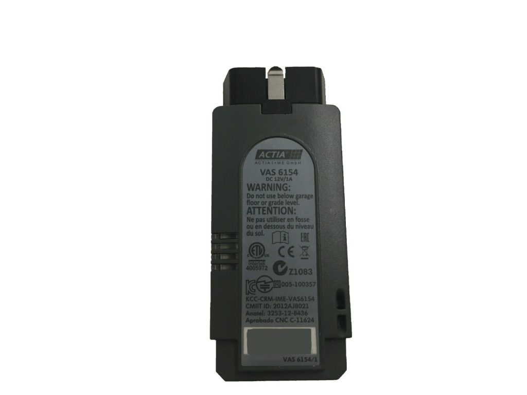
VW group OBD-II tools

First, If you are here to research before you buy, the post explaining everything not specific, but applies to VW is here.

VW- group cars include Volkswagen, Audi, Seat, Skoda, Bentley, MAN, Lamborghini, and Bugatti, all those vehicles use the same VW diagnostics software.

The software for VW cars is called ODIS and comes in 2 flavors, Service and Engineering (ODIS-S, and ODIS-E)

You don’t need all of the hardware to run the ODIS system as any windows based machine should replace most parts of the station, What you will need is a VCI pass-thru device.

In fact, you don’t need the original hardware at all for that purpose, Your laptop and a cheap passthrough device should do, for example, the GODIAG GD101 is a $20 passthrough piece that works with VWs own software

Legend:
Red = Complete system
Green = VCI passthrough plug

  • VAS5052A (Computer)
  • VAS5054 (VAS5052A) (VCI, OKI Chip, Bluetooth)
  • VAS5054A (VAS5052A) (VCI, OKI Chip, Bluetooth)
  • VAS6150B
  • VAS 6154A (Like B but different wifi chip)
  • VAS 6154B (VCI, ODIS-S 23.0.0 and newer only)
  • VAS6160A (VAS 6160 (Newer vehicles), VAS 5051 (Older vehicles), VAS 5052 (non-brand vehicles), VAS 5052A)
  • VAS6160C
  • VAS6150E-NV
  • VAS6150F (VAS6154B)
  • VAS6150F-NV

Cantact OBD

This special CAN BUS hardware (https://cantact.io/cantact/users-guide.html) is very nice in the sense that it lends itself to many possibilities, and this is why I am creating this separate post about it.

An alternative board is the https://canable.io/ board, but I will stick to the board I own for this post

The standard firmware for my Cantact is candlelight available at linklayer/candleLight_fw, And there is a firmware here (https://github.com/HubertD/candleLight), the official users manual page is here (https://cantact.io/) and here (https://github.com/linklayer/cantact-book)

Linklayer also provides some very nice tools such as (https://github.com/linklayer/cantact-app)

Now, with that out of the way, let us take a look at the board itself

microcontroller

etching reads…

stm32f
042CbTb
GH238 93
CHN 708

Which tells us that the microcontroller is an STM32, A great choice for such a device (See the wikipedia article linked)

On linux, can-utils is a great tool for this thing

I actually made a 3D model casing that fits the board perfectly, I will post it here when i find it

List of OBD-II and Automotive repair software

This is a list of software and hardware that are relevant to repairing and parts of cars and trucks

Terms and concepts

Obviously, all of this is missing many details that are mostly irrelevant to why you are reading this post, You are probably here to figure out what tools you will need, and that is what I will focus on.

  • PID: Parameter IDs: The test software sends IDs and expects error codes or information in return, Some IDs are mandated by the state, other IDs are specific to a manufacturer.
  • response (Ex: Error) codes: Just like the PIDs (The questions- sent by the testing instruments), some responses are mandatory standards and others are manufacturer or car specific.
  • J1979: A standard set of PID/Response codes of which many are mandatory for all vehicles mostly for emissions regulations purposes
  • J1962: A standard for the hardware connector plug you can see under your instrument panel (Under your dash, in the footwell), formally named The DLC (Data link connector), Starting 1996, the OBD-II (OBD2) connector with both its variants (OBDII-A for 12V and OBDII-B for 24V) should be available for all cars sold in the US. Although it is now universal, some cars in other parts of the world didn’t get them until a few years later.
  • ELM327 command protocol:
  • J2534: THE TOOL, A tool that supports the J2534 standard should be able to speak to the vehicle in all of the following protocols (ISO9141, ISO14230 (KWP2000), J1850, CAN (ISO11898), ISO15765, SAE J2610, and J1939 (2005+))
Continue reading “List of OBD-II and Automotive repair software”

Will changing my transmission fluid break it

So i have a 2008 Mercedes-Benz E 200 Kompressor 5G-Tronic (W211). being aware of the theory that changing transmission fluid after having 135K Kms on the car will break my transmission/gearbox and finding it hard to believe, I decided to try it myself.

Why I am doubting this theory

My theory is about the origins of “transmissions breaks when fluid is changed”, and why it is likely WRONG.

The origin of that theory is probably the number of people who have problems soon after changing transmission fluid, and basically there is nothing wrong with the theory in this regard but bear with me.

my counter theory is, when people change their transmission fluid at such high mileage, they are not exactly servicing the car on proper intervals, the reminder to change the fluid for them was probably that the transmission acting up, so the transmission is on it’s last leg, you change the fluid, but the fluid can’t save the transmission, it is too late, the dirt in the dirty transmission fluid was creating a bit of friction (and accelerating the wear in the process), the situation is bad enough that you went to change the fluid to see if that helps, the transmission keeps on deteriorating because it is already going in that direction, so what do you do, you blame the oil change ! “It was working at least before I changed the oil !”

So my car comes with the 1.8L M271 , My transmission is probably the 722.695.

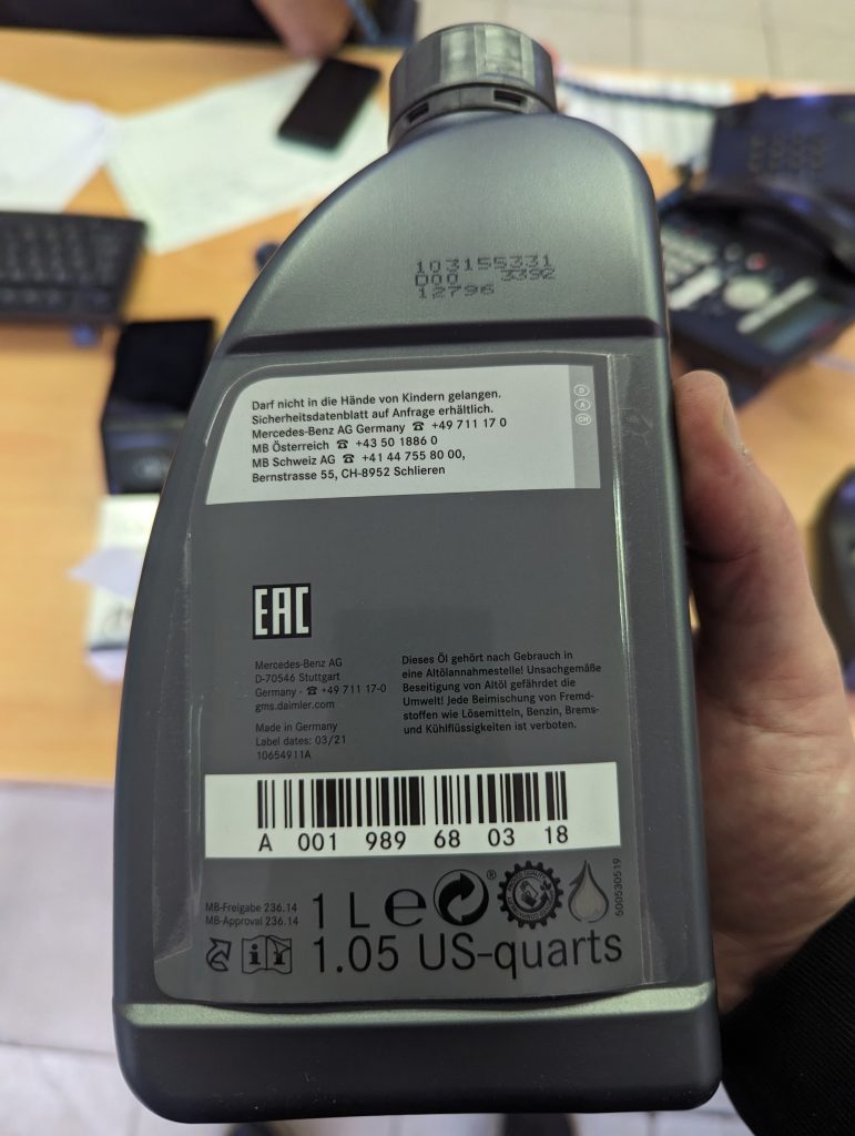
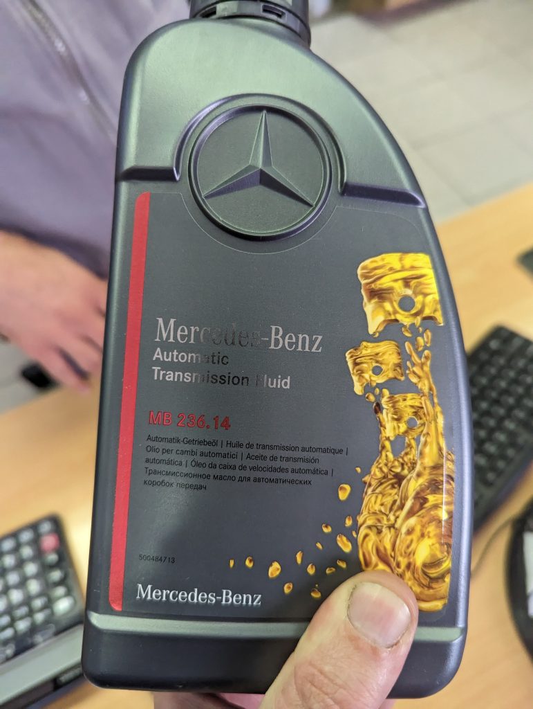
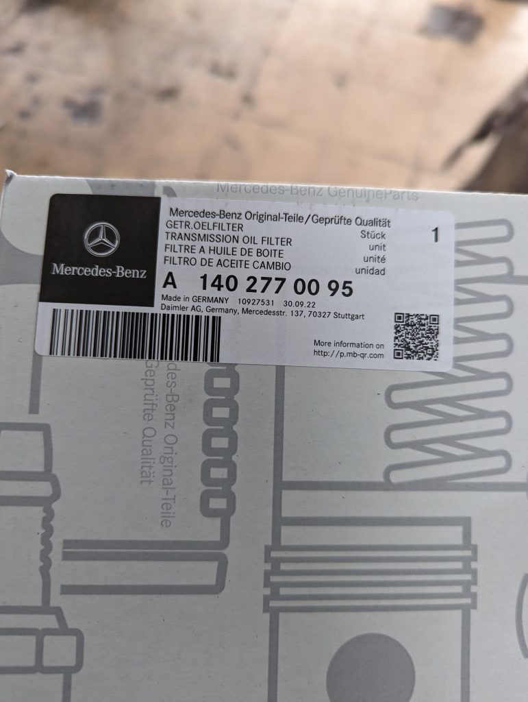
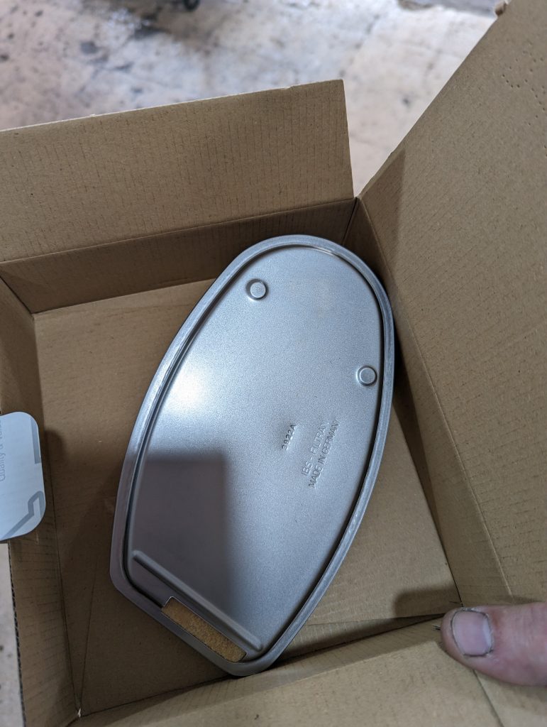
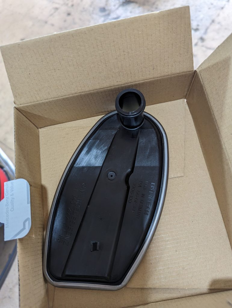
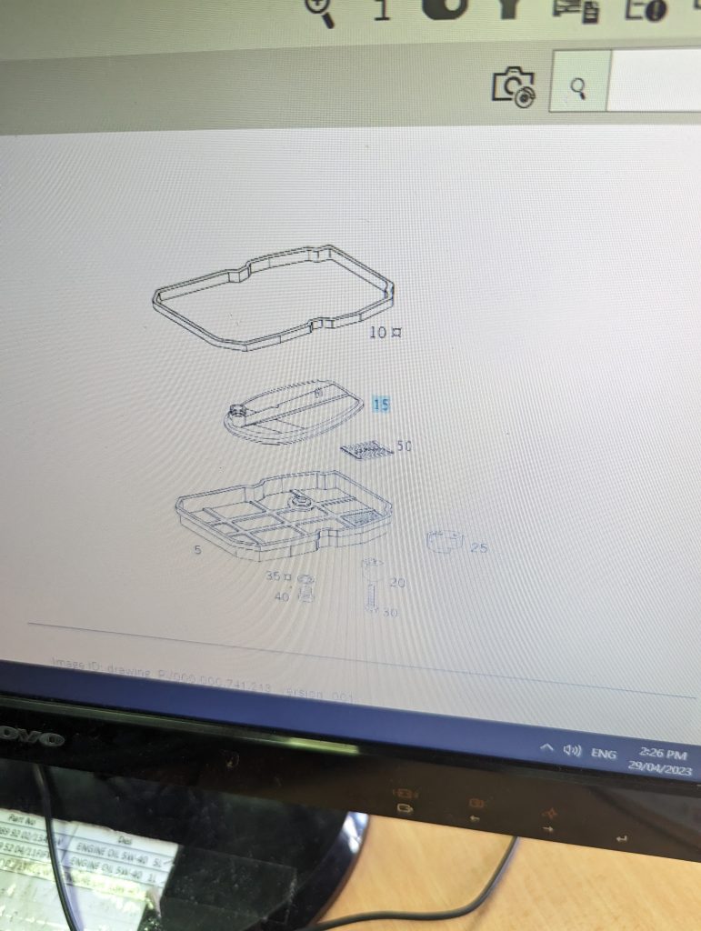
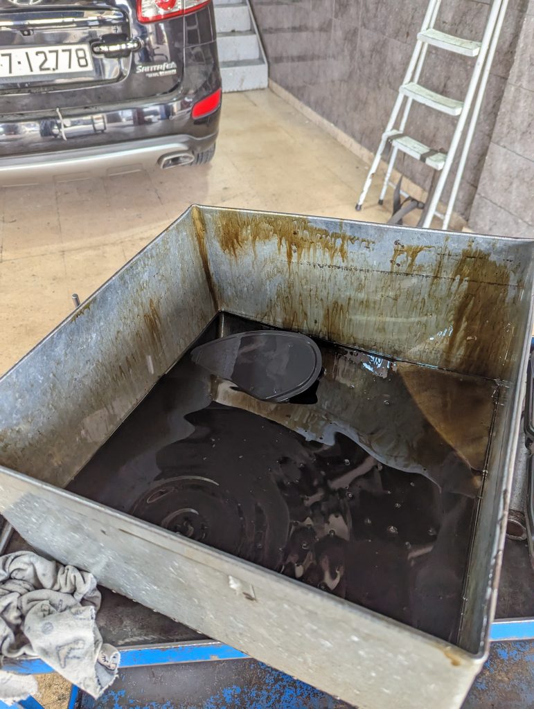
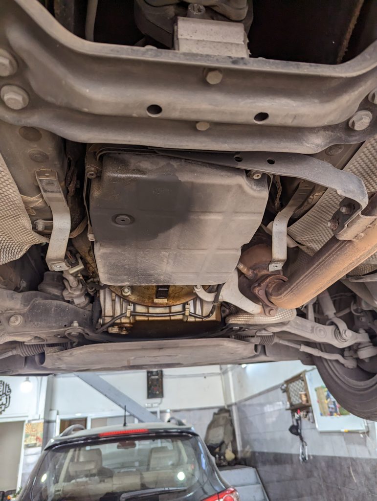
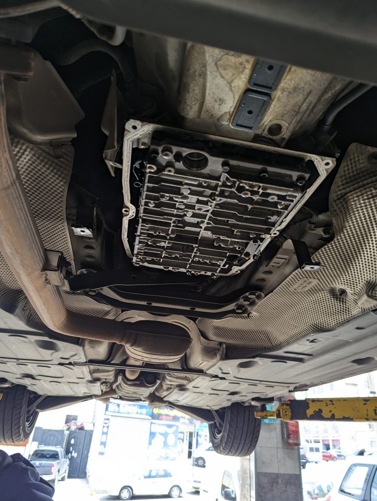
I have already drained 3Liters of fluid (All that was in the pan), and filled the transmission with 3 liters of Mercedes-Benz 236.14 transmission fluid, I have also replaced the oil filter and the pan gasket. there is a magnet stuck to the pan from the inside, be sure to clean that too !

Later on, I drained another liter and a half, and added a liter and a half, and kept half a liter to top it up once i find my relevant dipstick (Does not come with the car)

There are alternatives to the somewhat expensive MB fluid, but since i couldn’t find an MB certified one, or at least a fluid that claims to be the same, I decided to bite the bullet and go with the original.

UPDATE: After one year (today is April 19 2024), the transmission is working exactly the same as it was before changing the fluid, things seem to be going just fine.

Repairing the Prius HV traction battery

Attention: the stuff/information you need is at the beginning, Most of the stuff that follow the practical section you will not need (The some theory section), whatever more you see is for my reference, for the curious, and for those who are wondering why i do it this way.

The lowdown: I have successfully repaired my 2014 (3rd gen) Prius battery, despite the fact that most information on rebuilding your Prius battery online is Bull, almost as if it were engineered so that you kill the remaining good cells after a month or two.

Update Dec, 10 2024: The battery was rebuilt somewhere around the end of COVID, probably 2021 or early 2022 (Yes, i really don’t remember), it is still working perfectly on a car that commutes 200KMs per day, 5 days a week, besides its daily town use, proving beyond any doubt (in my mind) that i was right, YOU PAIR SIMILARLY HEALTHY BATTERIES AND DO NOT CONNECT WEAK BATTERIES WITH HEALTHY ONES, THE ADVICE ON THE INTERNET IS THE OPPOSITE OF WHAT YOU SHOULD DO…. Why this is follows in this post

Here are the tools you need

  • An android phone (You can use Apple/iPhone with torque pro, but the instructions here are for android)
  • The Torque Pro app on the phone
  • Prius PIDs for torque pro (Download here)
  • A compatible OBD2 adapter, I use a WiFi adapter, you can use a Bluetooth or any other that works with torque pro
  • A laptop with software like excel or LibreOffice calc, A paper and pen should also work
  • A charger capable of charging a battery of 6 NIMH cells (Battery means in series), I use the SKYRC imax B6 mini (I don’t, I use my own home made charger built with an arduino, a acs712 current sensor, and a screen, but for the purpose of this tutorial, we need a charger so the imax B6 mini should do the trick)
  • Car headlight lamps (To drain the batteries)

Like everyone else, it all started with CHECK HYBRID SYSTEM STOP THE VEHICLE IN A SAFE PLACE getting displayed on my center “multi information display / instrument panel” or MID for short.

Connecting the OBD2 adapter resulted in fault code (P0a80) other relevant codes might display with P0a80 such as p3011, p3012, p3013 etc. which should point you to the failing module pairs that are causing the failure. in my case, I only had the P0a80.

Prius battery terminology (As per Toyota)

Hybrid battery: the whole Prius traction battery pack of 28 modules
Module Pair: the car reads voltages of modules in pairs, So voltages of the 28 modules in a Prius battery are reported to the car as 14 values, meaning every 2 modules are read together as the sum of the voltage of those 2 modules.
Battery Module: in a Prius battery, every 6 cells are enclosed in a sealed container called a module, this is why you don’t directly see the cells, a module’s nominal voltage is 7.2, which is the nominal voltage of 1 cell multiplied by 6.
Battery Cell: A 1.2V NIMH cell that you will not see because it is hidden inside a module.

So, without further ado, let us get started

Diagnosis, which modules are bad

Before we take the battery out, we can save a hell lot of time by looking at what the car has to say about it’s battery pack.

I have broken this down to steps you see below

  • Install torque pro to your phone (android in my case)
  • Download the Prius 3rd Gen PIDs file by clicking here
  • extract the file you have just downloaded to the (/.torque/extendedpids) directory in your phone
  • Open torque pro, and go to the Menu -> Settings -> Manage extra PIDs/Sensors -> Menu -> Add predefined set.
  • Create an Realtime Information page in torque pro to display battery voltages in real time such as the one below, you start with an empty page, then add (tiny) displays corresponding to voltages of individual modules, I personally like to add the Min and Max voltage entries to make it easier to know when you have found what you are looking for while driving without having to scan through the batteries
  • Clear the error code, switch the car off then on again, the car should now appear to be working fine as if the battery is okay, this is obviously just for the test as the car will soon find out the problem again and inform you of your problem
  • Now, once connected and information is displayed, find a nice uphill climb that is not too steep, with no traffic, at the bottom of that climb, floor the break and gas pedal at the same time, this will charge the battery, then on EV, start climbing wile recording your phone screen, the battery should drain really fast and you will either hear the engine running, or the “Check hybrid system” message should appear again, either way, you now have a reading of which batteries drained very fast…
  • Inspect the recorded screen recording, and figure out which modules are the ones causing the problem, please note that there may be other modules in bad shape, but for now, the worst ones are clear

Taking the battery out of the car

To be able to pull the battery out of the car, you will need to take the following steps

Some theory

The 20% to 80%

Q: Why does the car consider the battery fully charged at 80%, and depleted at 20% of the batteries actual capacity ?

A- Why the 80% cap ?

Let us start with why it caps at 80% ! (At 80 percent, 100% will display on your instrument cluster)

The most common theory (that i don’t find convincing) is that the car wants to leave headroom for regenerative breaking, if it were so, why does it start using the gas engine’s breaking at 80% ? burning fuel, and defeating the purpose of regenerative breaking ?

My own theory is that there are multiple reasons, of which the headroom theory above is not one… here are the reasons i expect the car was designed this way

1- NIMH batteries heat up once you are charging above 80%, which is wasted energy, so the car is expected to try an use up the battery back down to the happy 6/8 area.
2- Heat is bad for the module’s health, and the health of the modules around it (See 1)
3- When modules in module pairs become mismatched health wise, this 20% headroom spares the weaker cell the overcharge and the damage associated with it., illustration will be added soon.

B- And the 20% depletion mark ?
NIMH cells can be depleted to ZERO, in fact, the company that makes the enelope batteries for Panasonic calls depleting the battery to zero and then charging it again a refresh function.

The area between 0.9V and zero volts has very little energy, as most energy is delivered between 1.3 and 1 volt, but still, this area is much less than 20% ! so why 20%

1- Unlike gas cars, hybrid vehicles do not have a 12V starter motor, the gas engine in a hybrid car is started by the electric motor itself, the same one used to propel the car is used to start the engine, if the battery falls below 20%, especially as batteries start to age, there will not be enough power to start the engine, more to that, the batteries have internal resistance, so the car needs to be sure that when it is parked for a few days (or months), it will have enough traction battery power to start the gas engine.